 The circuit presented here can provide up to three amperes of current for a 5V, 6V, 8V, or 9V supply. It uses the popular adjustable voltage regulator LM317, which is inexpensive and is used generally for variable power supplies with up to 1.5 ampere current.
With the addition of PNP transistor TIP127 in the circuit, we get a 5V to 9V variable power supply with 3A current rating. However, suitable heatsinks for LM317, TIP127, LM7809 and an exhaust fan for cooling the TIP127 are required.

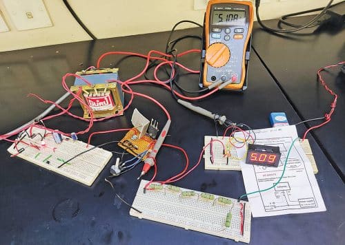
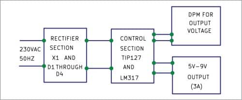
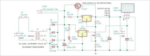
The author’s prototype is shown in Fig. 1. The block diagram of the variable power supply is shown in Fig. 2 and its circuit diagram in Fig. 3.


Circuit and working
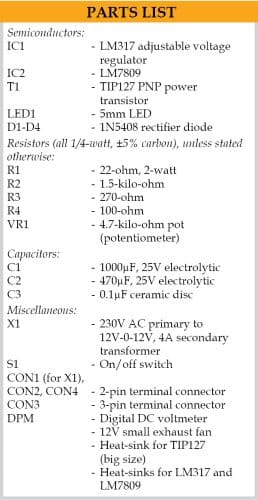
The variable power supply is built around step-down transformer X1, four 1N5408 rectifier diodes D1 through D4, an LED, TIP127 transistor T1, LM317 adjustable voltage regulator IC1, 9V voltage regulator IC2, and a DC digital panel meter (DPM). A 22-ohm, 2-watt resistor (R1) is connected between the base and emitter of T1 to control the current. Pot VR1 is used to control the output voltage. The output voltage can be seen on the DPM.
The output voltage can be set to 9V and the current drawn is around 3A. The voltage across resistor R1 makes transistor T1 to conduct and most of the current is drawn from emitter to collector of T1. As lesser current passes through LM317 and most of the current flows through T1, heatsink of IC1 is less warm as compared to the heat sink of transistor T1 heat sink. So the heat sink for T1 needs to be bigger than the heat sink for IC2 and IC3. Use of exhaust fan helps in proper dissipation of the heat. With more current needed by the load, transistor T1 conducts more and the current bypasses the LM317.

LED1 glows when 230V AC supply is on. VR1 is used to vary the output voltages according to your requirement. The voltage is shown on DPM.
Please register to view this article or log in below. Tip: Please subscribe to EFY Prime to read the Prime articles.


Excellent source but I am looking for how to design a variable source up to 80 volts. if someone can help me
Dear Victor,
Thanks for sharing your requirement with us.
We will try to design a variable source up to 80 volts for publishing
it in future issue.
Regards