Pianos and many other musical instruments have now been digitised. They can now be replicated using electronic circuits. This device converts traditional pianos or other instruments into digital forms using electronic components. The source code can be modified to create various digital instruments, such as drums or flutes, by adjusting the output sound, tone, and frequency.
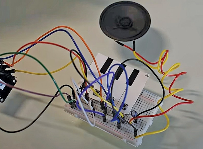
This device uses an ESP32 board for tone processing, with transistors amplifying the output. You can create or modify code in any IDE, such as Arduino IDE, ESP IDF, Micropython, or Smowcode. For quick coding, Smowcode has been used in this device. Fig. 1 shows the author’s prototype on a breadboard. The required components are listed in Bill of Materials table.
| Bill of materials | |
| Components | Quantity |
| ESP32 board | 1 |
| Speaker | 1 |
| 10µF capacitor | 1 |
| 100k resistor | 1 |
| BC547 transistor | 1 |
| Push buttons | 4 |
Circuit and Working
Fig. 2 shows the circuit diagram of the electronic piano, built around the ESP32 board, BC547 transistor, speaker, and other components.
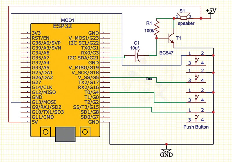
A breadboard is used for wiring. A 100-kilo-ohm resistor is connected between base and collector of transistor T1. Capacitor C1’s negative terminal connects to the base of T1 and the positive terminal connects to pin G21 of the ESP32 board (MOD1). One terminal of the speaker connects to the 5V pin of the ESP32 and the other connects to T1’s collector. The emitter of T1 is connected to the ground of the ESP32.
The four push buttons are grounded by one terminal, while the other terminals connect to pins G13, G4, G5, and G15 of the ESP32 board. The ESP32 controls sound frequency and produces different sound frequencies based on the buttons pressed.

Construction and Testing
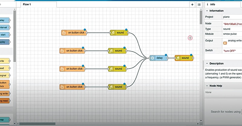
You can either download the firmware in .bin format from the website and upload it to the ESP32 board, or quickly modify and create code by connecting the nodes. Once the code blocks are set (see Fig. 3), upload the code to the board by selecting the correct COM port and board.
First, upload the source code to the ESP32 board. Then assemble the device on the breadboard, as shown in the wiring diagram in Fig. 4. Power the device and press the buttons to play different tones, which can be modified as desired.
Faiza Shaikh is an electronics enthusiast.


