Most multimeters make voltage measurements starting from one volt and some start from 200 millivolts. With such devices lower-value measurement becomes difficult, especially for DIY projects. Here is a circuit that can measure low voltages, starting one millivolt onwards, with better resolution.
Circuit and working
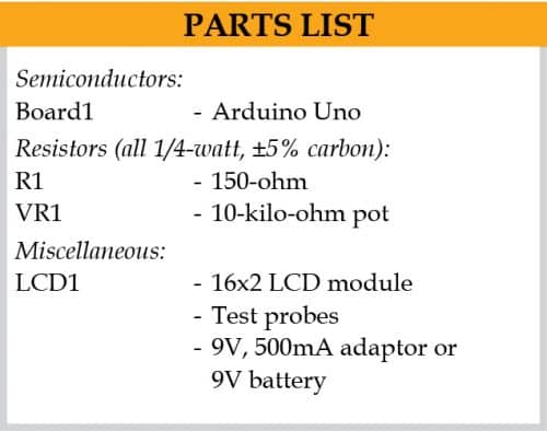
Circuit diagram of the millivolt meter is shown in Fig. 1. It is built around Arduino Uno board (Board1) and 16×2 LCD display (LCD1).
The voltage to be measured is applied at analogue input pin A0 of Board1 through test probes T1 and T2. The analogue reference voltage is changed to internal 1.1V for better resolution.

The Arduino is the brain of the circuit that calculates the voltage based on the ADC value using the program, which is displayed on LCD1. The voltage at analogue pin A0 should not exceed 1V. If it does, ‘Over range’ alert message is displayed on LCD1.
Arduino Uno is a popular open source microcontroller development board based on ATmega328P microcontroller. It has fourteen digital input/output (I/O) pins, six of which can be used as PWM outputs and six as analogue inputs. It includes a 16MHz crystal, USB connector, power jack, and ICSP header and comes with pre-loaded Arduino bootloader in its ATmega328P chip.
 Construction and testing
You can assemble the circuit on a PCB or breadboard. The Arduino can be powered by an external 9V battery or a 9V, 500mA adaptor. After uploading the source code (mV_Meter.ino) to Board1, connect it to LCD1. Use test probes for better accuracy and low attenuation.
Note. This circuit measures only low voltages of 1mV to 1V. Do not try to measure negative voltages, or reverse the polarity of the cable, as it would destroy the Arduino. There may be a small tolerance (deviation) in the readings due to parasitic elements in the PCB.
Download Source Code
A. Samiuddhin, a circuit designer, is B.Tech in electrical and electronics engineering. His interests include LED lighting, power electronics, microcontrollers, and Arduino programming


Simple Millivolt Meter Using Arduino
help please as the code wont compile ( ‘INTERNAL’ was not declared in this scope)
thanks