 Monitoring circuits in battery chargers, water-level indicators, etc use LEDs to indicate the status of certain conditions. Presented here is a multiple status indicator circuit that uses a single RGB LED for seven different indications.
Circuit and working for Multiple Status Indicator Using Single RGB LED
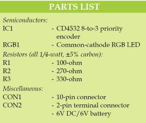
Circuit diagram of the multiple status indicator using a single RGB LED is shown in Fig. 1. It is built around priority encoder CD4532 (IC1), common-cathode RGB LED (RGB1) and a few other components. IC CD4532 is an 8-to-3 priority encoder that converts 8-bit data inputs (D0 through D7) into 3-bit binary data (Q0 through Q2).
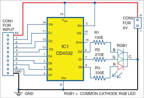
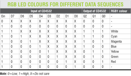
The RGB LED is connected to the binary output of IC1. For every high output (5V) of IC1 at data pins Q0 through Q2, the LED emits different colours for different data sequences as given in the table. Resistors R1 through R3 are used to limit the current flowing through the LED, one for each colour. With a single RGB LED, up to seven different states can be indicated through different colours. The data sequence is given in the table.
Construction and testing
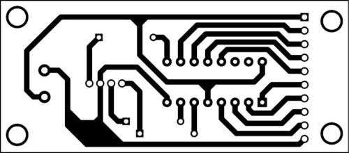
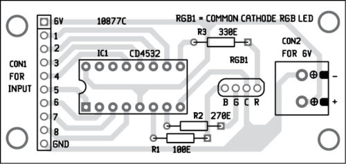
An actual-size PCB layout of the multi-status indicator using a single RGB LED is shown in Fig. 2 and its components layout in Fig. 3.
Download PDF and Component Layout PDFs: click here
This circuit can be powered by a 6V battery or regulated 6V DC supply. Different combinations of high (5V) and low (0V) inputs are given to the digital input of IC1 (across CON1) as listed in the table. Enclose the circuit in a small plastic box. IC1 can be cascaded with another IC for more inputs.
A. Samiuddhin is B.Tech in electrical and electronics engineering. His interests include LED lighting, power electronics, microcontrollers and Arduino programming


