This project presents an Arduino based speed monitoring system where the RPM (revolutions  per minute) of a DC motor is continuously displayed on a smartphone using Bluetooth communication.
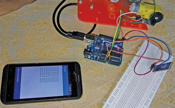
The Arduino programming employs an interrupt service routine to determine the motor speed. The authors’ prototype of the project is shown in Fig. 1.

Circuit and working
The main components used in this project are:
Arduino Uno. Arduino Uno is an AVR ATmega328P microcontroller based development board with six analogue input pins and fourteen digital I/O pins. The microcontroller has 32kB ISP flash memory, 2kB RAM, and 1kB EEPROM.
Speed sensor. In this project, an opto-coupler based speed sensor module is used. This type of sensor generates square wave of a certain frequency which depends on the speed of motor. Opto-coupler module FC-03 was used during testing.
Coded disc encoder. It has some holes which help the opto-coupler type of speed sensor to generate the square wave as mentioned above. A coded disc encoder with twenty holes is used in this project.
Bluetooth module. The popular HC-06 Bluetooth module used for this project sends the data from Arduino Uno to the Android based smartphone. You can also use HC-05 Bluetooth module in place of HC-06.
Arduino Bluetooth controller. This software is based on the Android platform and helps in communication of the smartphone with the HC-06 Bluetooth module. Arduino Bluetooth Controller by Giumig Apps was used during testing.

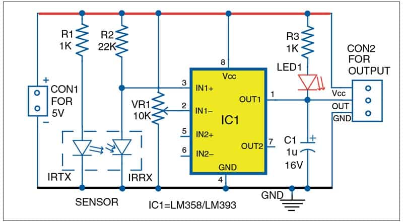
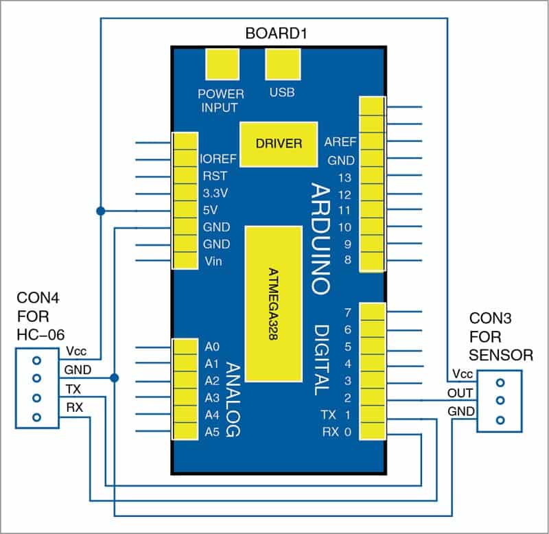
The internal circuit diagram of the opto-coupler type speed sensor module (FC-03) is shown in Fig. 2. The circuit diagram for the monitoring of the motor speed on smartphone using Arduino Uno is shown in Fig. 3.

As shown in Fig. 3, the output of the speed sensing module is connected to digital pin 2 (D2) of the Arduino. Using an interrupt based approach, we can detect the pulse produced by the sensing module (in every ten seconds), which depends on the speed of the motor. Since there are twenty holes in the coded disc, the speed (in RPM) =((pulse×6)/20).
After determining the motor speed, the Arduino sends this data to the smartphone (to display) via the Bluetooth module. Pin TX of the Arduino is used for this purpose.
Software
The source code is written in Arduino programming language. The ATmega328/ATmega328P is programmed using the Arduino IDE software.
Select the correct board from Tools → Board menu in Arduino IDE and burn the program (sketch) through the standard USB port in your computer. Here, Serial.begin(9600) function initialises the serial port with a baud rate of 9600. The attachInterrupt(0,counter,FALLING) function calls the interrupt handler “counter” whenever a signal connected to interrupt pin 0 of the Arduino makes a high-to-low, that is, falling edge transition.
After uploading the code to Arduino board (Board1), connect HC-06 Bluetooth to CON4 and sensor digital output to CON3. Mount the disc encoder wheel on the shaft of the DC motor. Place the disc encoder between the groove of the opto-sensor, as shown in the prototype above.
Pair the Bluetooth between the smartphone and HC-06. Open the Arduino Bluetooth Controller app from an Android phone and select Terminal Mode. Now switch on the motor. As the encoder disc rotates between the optical encoder groove, the RPM of the motor can be read on the smartphone. The RPM can also be read on the serial monitor of Arduino.
Download Source Code
Souvik Kumar Das is passionate about electronics and MCU-based system design
Shibendu Mahata is M.Tech (gold medallist) in instrumentation and electronics engineering from Jadavpur University. He has several publications in the domain of signal processing in reputed internationals journals and conferences to his credit


